- Set switch on Altera Board to "DOWN" (where the power connection is "UP").
- Connect the power cable to power supply and parallel cable from PC to Byte Blaster cable on ALTERA Board.
- Open Quartus and go to the programmer.
- Click on the Hardware button and select "ByteBlasterMV [LPT1]"
- Click add file and select maxtest.pof
- The Mode should be set to "JTAG", and the boxes under "Program/Configure", "Verify", "Blank-Check", and "Security Bit" should be checked.
- Click Program.
- If you get a "JTAG ID code specified in Jam File does not match any valid JTAG ID codes for device", make sure the power is on and that the switch is set to "DOWN". If it fails again, take the board to BA3110 to for replacement.
- Connect the 60 pin ribbon cable from the 60 pin header opposite the EMP7128 to the AlteraTest Board.
(The Altera Test Board should be in the cabinet with all the Altera Boards)
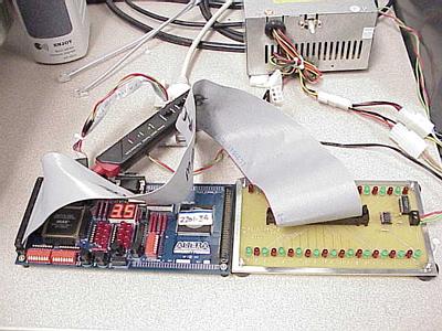
The LEDs on the Test Board will go through a test routine.
Check to see if any of the LEDs are always ON or OFF
The test program checks:
- Each individual I/O pin
- Both odd and even I/O pins at the same time
- The even I/O pins are all ON.
- The odd I/O pins are all ON.
- All the I/O pins are ON.
The pattern repeats the sequence again.
If the test fails check the 60 pin ribbon cable.
Try the test again.
If the cable or Altera Board are bad get another from Norm Baccari in the B3110
- Set switch on Altera Board to "UP" (where the power connection is "UP").
- Connect the power cable to power supply and parallel cable from PC to Byte Blaster cable on ALTERA Board.
- Open Quartus and go to the programmer.
- Click on the Hardware button and select "ByteBlasterMV [LPT1]"
- Click add file and select max10k70.sof
- The Mode should be set to "JTAG", and the box under "Program/Configure" should be checked.
- Click Program.
- If you get a "Can't configure device. Expected JTAG ID code 0x010700DD for device 1, but found JTAG ID code 0x071280DD", make sure the power is on and that the switch is set to "DOWN". If it fails again, take the board to BA3110 to for replacement.
- Connect the 60 pin ribbon cable from the 60 pin header opposite the FLEX 10k70 to the AlteraTest Board.
(The Altera Test Board should be in the cabinet with all the Altera Boards)
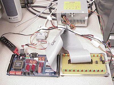
The LEDs on the Test Board will go through a test routine.
Check to see if any of the LEDs are always ON or OFF
The test program checks:
- Each individual I/O pin
- Both odd and even I/O pins at the same time
- The even I/O pins are all ON.
- The odd I/O pins are all ON.
- All the I/O pins are ON.
The pattern repeats the sequence again.
If the test fails check the 60 pin ribbon cable.
Try the test again.
If the cable or Altera Board are bad get another from Norm Baccari in the B3110