Audio Core
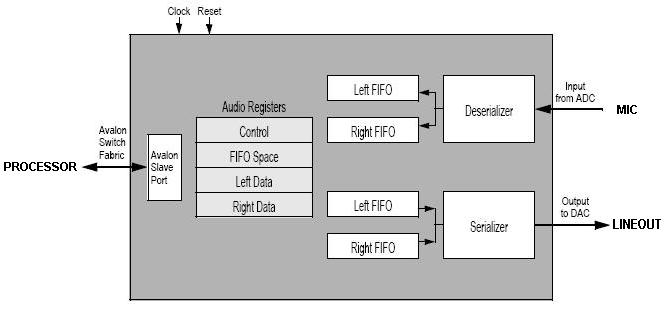
The Audio Core is a circuit which simplifies communication between the Nios
II processor and the Audio CODEC responsible for converting sound into digital
values (enCOding) and vice versa (DECoding). It is essentially 2 pairs of
FIFOs (so 4 in total) each 128 entries deep with each pair responsible for
sending/receiving samples to/from the LINEOUT/MIC. They are pairs because
there are two different channels, left and right, allowing for stereo sound
(stereo sound means the left and right speakers can play different sounds,
while mono sound means they both play the same). To better understand how
analog input is converted to digital bits read the following documentation
understanding sound .
See the image below for a
diagram of the Audio Core and its FIFOs.
| Device | Audio Core |
| Configuration | 32-bit signed integer samples, two-channel, 48 KHz sampling rate, 128 sample FIFO |
| Input/Output | Both |
| Address Base | 0xFF203040 |
| Address Map |
| Address | R/W | Description |
| base | R/W | Control Register for clearing FIFOs and interrupt control/status. See Note 1 |
| base+4 | R/W | Fifospace Register tells you how much space is in each of the 4 FIFOs. See Note 2. |
| base+8 | R/W | Left Data, reads read from the MIC FIFO, writes write to the LINEOUT FIFO. |
| base+12 | R/W | Right Data, reads read from the MIC FIFO, writes write to the LINEOUT FIFO. |
|
| Initialization | None |
| Interrupts |
| Triggered | Read Interrupts - when either left/right FIFO is 75% or more filled.
Write Interrupts - when either left/right FIFO is 75% or more empty |
| IRQ Line | 6 |
| Enable | In Control Register set bits 1 (WE) and 0 (RE) for write and read interrupts respectively. |
| Acknowledge | Interrupts will keep reoccurring until FIFOs are below/above the 75% mark. See Note 3 |
|
| Hardware Setup | Plug the microphone into the MIC port, and the speakers into the LINEOUT audio port. The LINEIN port is played back on LINEOUT, but is otherwise unused (not recorded). |
| Reference |
Audio Core Datasheet
WM8731 Audio CODEC Datasheet |
Notes
- The Control Register uses only the least significant 6 bits as follows:
| Bit | Name | Description |
| 0 | RE | Read Interrupt enable |
| 1 | WE | Write Interrupt enable |
| 2 | CR | Clear both left and right read FIFOs |
| 3 | CW | Clear both left and right write FIFOs |
| 8 | RI | Indicates that a read interrupt is pending |
| 9 | WI | Indicates that a write interrupt is pending |
- The Fifospace Register stores how much space is in each of the 4 FIFOs. The register is 32-bits wide and since each FIFO has only 128 entries, the Fifospace register can store all 4 of the 8-bit values.
| Bits | Name | Description |
| 7:0 | RA RC | Read data Available in Right Channel |
| 15:8 | RA LC | Read data Available in Left Channel |
| 23:16 | WS RC | Write Space in Right Channel |
| 31:24 | WS LC | Write Space in Left Channel |
- There is no Interrupt Acknowledge, you simply need to make sure that for
every interrupt you appropriately pop/push something to/from the violating
FIFO. As long as your Interrupt Service Routine is faster than the 48KHz of
the CODEC, the processor will equilibrate with the CODEC and interrupt only
once with every new sample. The Nios processor runs about 2000 times faster
than the CODEC's sampling rate, so avoid executing more than 2000 instructions
in your ISR per sample processed.
-
The LINEIN port is echoed back out LINEOUT in hardware, but is not recorded.
This configuration can be changed by editing the DE1-SoC Computer and rebuilding it.
IMPORTANT: You must always write to both left and right FIFOs. If either FIFO is empty, nothing is sent to the Audio CODEC.
Assembly Example: Echo program - connects mic to speakers, polling
.equ ADDR_AUDIODACFIFO, 0xFF203040
main:
  movia r2,ADDR_AUDIODACFIFO
  ldwio r3,4(r2)      # Read fifospace register
  andi  r3,r3,0xff    # Extract # of samples in Input Right Channel FIFO
  beq   r3,r0,main    # If no samples in FIFO, go back to start
  ldwio r3,8(r2)
  stwio r3,8(r2)      # Echo to left channel
  ldwio r3,12(r2)
  stwio r3,12(r2)     # Echo to right channel
  br main
C Example: Echo program - connects mic to speakers, polling
// We're lazy: Read only from right channel.
int main()
{
	unsigned int fifospace;
	volatile int * audio_ptr = (int *) 0xFF203040; // audio port

	while (1)
	{
		fifospace = *(audio_ptr+1); // read the audio port fifospace register
		if ((fifospace & 0x000000FF) > 0 &&		// Available sample right
			(fifospace & 0x00FF0000) > 0 &&		// Available write space right
			(fifospace & 0xFF000000) > 0)		// Available write space left
		{
			int sample = *(audio_ptr + 3);	// read right channel only
			*(audio_ptr + 2) = sample;		// Write to both channels
			*(audio_ptr + 3) = sample;
		}
	}
}