The Lego Controller can be plugged into either the JP1 or JP2 40-pin expansion headers, and allows the user to control up to 4 motors (turning them ON/OFF and changing their direction), and read the values of up to 4 light sensors. For a detailed explanation of the bit-mapping, please refer to the Notes section.
| Device | Lego Controller | ||||||||||||||||||||||||
| Input/Output | either | ||||||||||||||||||||||||
| Address Base | JP1: PortA=0xff1110, PortB=0xff1120, PortC=0xff11b0 JP2: PortA=0xff1130, PortB=0xff1140, PortC=0xff11c0 | ||||||||||||||||||||||||
| Address Map |
Motors:
Sensors:
| ||||||||||||||||||||||||
| Initialization | Set the direction register of the motors (port A) to 0xff (all outputs). Set the lowest 4 bits of the direction register of the sensors (port B) to 0 (inputs). The highest 4 bits are not used; hence, it is possible to simply write 0x00 into this direction register. | ||||||||||||||||||||||||
| Interrupts |
| ||||||||||||||||||||||||
| Hardware Setup | Connect the 40-pin ribbon from the Lego Controller to either port JP1/2 on the DE2 | ||||||||||||||||||||||||
| Reference |
Lego Manual Old Lego Manuals on-line |
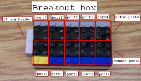
The Lego Controller is used to provide an easy interface to the motors and light sensors in the Lego kit. It has two override switches that can turn motors off (one switch for motors 1 and 2, and a second switch for motors 3 and 4). Each of the 4 sensor ports has a potentiometer ("pot"), which can be used to adjust its sensitivity. Make sure that these pots are set correctly for your needs. Lastly, there are two power connectors, providing 5V and 9V. The 5V connector can be used to connect to a motor, and the 9V connector connects to a special Lego piece, and can be used to power a light. Both power connectors can be switched off using a switch located close to them.
Controlling the motors - The motors are controlled by writing to the Data Register designated for them (see table above). The controlling bits come in pairs, and lower bits correspond to lower-numbered motors. In each bit pair, the lower bit is used to turn the motor ON and OFF (0 = OFF, 1 = ON), and the higher bit is used to choose one of two possible directions of rotation. The actual directions depend on the polarity of the connections to the motors. Refer to the diagram below for more information.
Reading the sensors - Reading the light sensors is done by reading the value of the Data Register designated for them (see table above). Only the lowest 4 bits of the byte are used, and lower bits correspond to lower-numbered sensors. For example, bit 0 corresponds to sensor #1, bit 1 corresponds to sensor #2, etc. The values of the sensors are active-high (i.e., a light shining on a particular light sensor would cause the corresponding bit to be 1).
Interrupts - Interrupts are triggered when any bit in the Edge Capture Register is high. For the Lego Controller this means an interrupt gets generated whenever light is shining on a connected sensor.
Relationship to the parallel interface - As described above, the communication with the Lego Controller is done using either one of the two parallel interfaces (JP1 or JP2). Using an alternate terminology, it can be said that for a particular parallel connector, motors are controlled through port A of the parallel interface, and sensors are read through port B.
The table below shows how the pins of ports A and B of the parallel interface connect to the motors and sensors of the Lego Controller.
|
|
.equ ADDR_PORT1A, 0xff1110	 /* port A: used to control the motors */
.equ ADDR_DIR1A, 0xff1114            /* port A: I/O direction */

  movia  r2, ADDR_DIR1A              /* set PORTA (motors) for output */
  movi   r3, 0xff
  stbio  r3, 0(r2)

  movia  r2, ADDR_PORT1A             /* r2 points to port A (motors) */
  movi   r3, 1
  stbio  r3, 0(r2)                   /* Set ON bit for motor #1, rest low */
.equ ADDR_PORT1B, 0xff1120	 /* port A: used to control the motors */
.equ ADDR_DIR1B, 0xff1124            /* port A: I/O direction */

  movia  r2, ADDR_DIR1B              /* set PORTB (sensors) for input */
  stbio  r0, 0(r2)

  movia  r2, ADDR_PORT1B             /* r2 points to port B (sensors) */
  ldbio  r3, 0(r2)                   /* Read sensor data port into r3 */
#define ADDR_PORT1A 0xff1110
#define LegoMotors ((volatile char *) ADDR_PORT1A)

int main()
{
   // init lego motor interface directions
   *(LegoMotors+4) = 0xff; //set all bit directions to output

   *LegoMotors = 0x01; //set motor 1 on

}