Lego Controller
***NOTE*** This is a quick reference for the Lego controller. For a
more detailed description of the Lego controller see Lego manual. You should also first read
and understand the operation of the GPIO devices
JP1/JP2.
The Lego Controller can be plugged into either the JP1 or JP2 40-pin expansion
headers, and is controlled by reading or writing to the GPIO port. The first 10 bits (0 to 9)
are used to control up to 5 motors, turning them ON/OFF and changing their
direction. Bits 10,12,14,16,18 are used to enable up to 5 sensors. Bits 27 to 30 have a dual function.
They can be used to read sensor data or indicate a state value of high or low depending on the threshold value. Bit 31 is used to determine the state value of sensor 5.
Bits 23 to 26 are used to load a threshold value, depending on which sensor is selected.
Bits 11,13,15,17 and 19 are used as acknowledge hand shaking bits for each of the sensors in polling mode. The board also features 5 HEX displays which display the
values being read by the sensors.
Since the Lego controller is controlled through a single GPIO port, certain bits will be configured as both inputs and outputs. When reading inputs, it will thus be necessary to use masking to get valid data. Similarly, when writing to the outputs, care will have to be taken to keep any bits you do not want changed the same.
| Device | Lego Controller: connected via JP1 or JP2 |
| Input/Output | both |
| Address Base | JP1: 0xFF200060; JP2: 0x0xFF200070 |
| Address Map: Value Mode |
| Address | R/W | Description |
| base | R/W | Data Register:
| Description: | Sensor Values and control bits | Sensor Control | Motor Control |
| sensor5 | Sensor Value | Threshold value |
Load Threshold | Mode | Unused | Ready sensor4 | Sensor4 | Ready sensor3 | Sensor3 | Ready sensor2 | Sensor2 | Ready sensor1 | Sensor1 | Ready sensor0 | Sensor0 | Motor4 | Motor3 | Motor2 | Motor1 | Motor0 |
| Bit: | 31 | 30 | 29 | 28 | 27 | 26 | 25 | 24 | 23 | 22 | 21 | 20 | 19 | 18 | 17 | 16 | 15 | 14 | 13 | 12 | 11 | 10 | 9 | 8 | 7 | 6 | 5 | 4 | 3 | 2 | 1 | 0 |
| Usage: | - |
sensor read value | - | - | - | - | - | state/
value | - | valid/
not valid | on/
off | valid/
not valid | on/
off |
valid/
not valid | on/
off | valid/
not valid | on/
off | valid/
not valid | on/
off | for/
rev | on/
off | for/
rev | on/
off | for/
rev | on/
off | for/
rev | on/
off | for/
rev | on/
off |
|
| base+4 | W | Direction Register: 0x07f557ff
Bits 26 downto 21 and 18,16,14,12,10 downto 0 must be set to 1's outputs
Bits 31 downto 27,19,17,15,13,11 must be set to 0's inputs.
Bit 19,17,15,13,11 are used to detect if sensor data is valid. Sensor data is valid when low
|
Note: load=0, don't-load=1; state=0, value=1; forward=0, reverse=1; on=0, off=1
Note2: the actual direction of a motor depends on the polarity that you connect it
|
| Address Map: State Mode |
| Address | R/W | Description |
| base | R/W | Data Register:
| Description: | Sensor Values and control bits | Sensor Control | Motor Control |
| State4 | State3 | State2 | State1 | State0 | Threshold value | Load Threshold | Mode | Unused | Ready sensor4 | Sensor4 | Ready sensor3 | Sensor3 | Ready sensor2 | sensor2 | Ready sensor1 | Sensor1 | Ready sensor0 | Sensor0 | Motor4 | Motor3 | Motor2 | Motor1 | Motor0 |
| Bit: | 31 | 30 | 29 | 28 | 27 | 26 | 25 | 24 | 23 | 22 | 21 | 20 | 19 | 18 | 17 | 16 | 15 | 14 | 13 | 12 | 11 | 10 | 9 | 8 | 7 | 6 | 5 | 4 | 3 | 2 | 1 | 0 |
| Usage: | below/
above |
below/
above | below/
above | below/
above | below/
above |
threshold write value | load/
don't load | state/
value | - | valid/
not valid |
on/
off | valid/
not valid | on/
off | valid/
not valid | on/
off | valid/
not valid | on/
off | valid/
not valid | on/
off | for/
rev | on/
off | for/
rev | on/
off | for/
rev | on/
off | for/
rev | on/
off | for/
rev | on/
off |
|
| base+4 | W | Direction Register: 0x07f557ff
Bits 18,16,14,12,10 downto 0 must be set to 1's outputs.
Bits 31 downto 27,19,17,15,13,11 must be set to 0's inputs.
|
| base+8 | W | Interrupt Mask Register enables interrupts for each pin (the corresponding pins should be configured as input). Eg., set to 0xf8000000 to allow interrupts on any sensor |
| base+12 | R/W | Edge Capture Register, a bit is high if corresponding pin changed its value from 1 to 0. Writing here clears all bits. |
Note: at or above=1, below=0; load=0, don't-load=1; state=0, value=1; forward=0, reverse=1; on=0, off=1
Note 2: the actual direction of a motor depends on the polarity that you connect it
|
| Interrupts for State Mode |
| Enable | Set bits in Interrupt Mask Register that correspond to data bits you want to interrupt on |
| Triggered | Negative edge: When an interrupt enabled input data bit changes from value of '1' to a value of '0' (From "above" to "below" threshold) |
| IRQ Line | JP1: 11; JP2: 12 |
| Acknowledge | Write to Edge Capture Register (which clears it) |
|
| Reference | Lego Controller Manual |
Hardware Setup
- Connect the 9 volt DC power supply to the Lego controller.
- Make sure the slider switch at the bottom and centre of the Lego controller
board is in centre position. If it is not, the Lego controller will not work
properly with the DE1-SoC board. For more information on slider switch modes
see the Lego manual section on
Slider Switches .
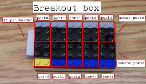
- Connect the Lego controller to the break-out box using the 16 pin ribbon cable.
- Connect the Lego controller to the DE1-SoC board using the 40 pin ribbon cable.
- Connect the motors and sensors to the break-out box using the 2x2 black
connector blocks. See the picture below for the corresponding connections
on the break-out box.
The sensor interface works in two modes: value mode and state mode.
Sensors: Value Mode
Value
mode is the default.
In Value mode, one sensor is selected at a time using bits 18,16,14,12,10 then the 4-bit
value of the selected sensor can then be read on bits 30 downto 27. In value mode sensors
can only be read one at a time. Reading a sensor value requires two steps:
- Enable a sensor: tell the Lego controller which sensor you want to
read by writing to the bits of 18,16,14,12,10. Write a 0 for the corresponding
sensor you want to enable (write 1 for the rest). At the same time you should
have Mode set to "Value" and Load Threshold set to "Don't Load"
- Read the sensor: read the bits 30 downto 27 to get the current
value of the selected sensor. In order to have valid data the corresponding sensor ACK bit 19,17,15,13,11 must be low.If it is not low data at 30 downto 27 may not be valid
Sensors: State Mode
In State mode, 4-bit threshold values are uploaded for each sensor. Bits 18,16,14,12,10 are
used to select the sensor and bits 26 downto 23 are used to write the threshold value.
Loading threshold values must be done in Value mode. When the mode is switched
to State mode, bits 31 downto 27 will display the current "state" of
all 5 sensors. When a sensor reads a value greater than or equal to the
threshold it will set its corresponding bit to a 1, otherwise that bit will be
0. By using the interrupt feature of the GPIO ports you can set an interrupt
to trigger when a sensor decreases past its threshold value (negative edge).
In State mode, all 5 sensors can be read at once, but each sensor only
returns one bit indicating whether it is: at/above threshold or below
threshold. Threshold
values for each sensor need to be loaded into the Lego controller
beforehand. Threshold values can only be loaded one at a time.
Loading a threshold value
requires three steps:
- Enable sensor for loading: tell the Lego controller which
sensor will get the threshold value by writing to bits 18,16,14,12,10. Write a 0 for the corresponding sensor that you want to enable (write
1 for the rest). At the same time you should have Load Threshold set to "Load"
and Mode set to "Value"
- Write threshold value: write the 4-bit threshold value to bits 26 downto 23.
- Disable sensor for loading: tell the Lego controller the
threshold value has been loaded by disabling all sensors and setting Load
Threshold to "Don't Load".
Once all the sensors have been given a threshold value you can set Mode to
"State" by writing to bit 21. Then to check the state of the sensors, read bits 31 downto 27. A value of 1 means the corresponding sensor is at/above
its threshold value and a value of 0 means its below its threshold.
Interrupts (in State Mode)
When using the Lego controller in State Mode we can set interrupts to trigger
any time a sensor value has passed its threshold value. To do this we use the
interrupt feature of the GPIO. Before enabling interrupts make sure that the
sensors are setup for State Mode.
To enable interrupts for the sensors do the following:
- Enable Interrupts for each desired sensor using the interrupt mask register. This means setting bits 31 downto 27 of the IMR appropriately.
- Enable interrupts for IRQ11 or IRQ12 using ctl3.
- Enable interrupts globally using ctl0.
In the interrupt handler routine you can check which sensor triggered the
interrupt by reading the edge capture register.
NOTE: It is possible for two sensors to interrupt at once. Also, a sensor
that is not enabled for interrupts will still cause its corresponding bit on
the edge capture register to go high.
Remember to clear the edge capture register before exiting the interrupt hander routine.
Notes on Using the Lego Controller
The Lego Controller we are interfacing with views its inputs as coming from GPIO port 0 or 1. Bits 9 downto 0 controls up to 5 motors, bits 18,16,14,12,10 controls up to 5 sensors, bits 19,17,15,13,11 are sensor acknowledge bits and bits 30 downto 27 reads the sensor data. However, from the perspective of the software, you have only a single port available to control the device, as described above.
This means you must exercise great caution when using the device, specifically when controlling the sensors.
One possible strategy to manage sensor and motor control bit values is to designate a register that will hold the state of the motors and sensors. Modify this register to control the motors, and then write that register to the Lego controller.
Assembly Example: Assuming Lego controller plugged into JP1, turn motor0 on, forwards
  .equ ADDR_JP1, 0xFF200060   # Address GPIO JP1
  movia  r8, ADDR_JP1

  movia  r9, 0x07f557ff       # set direction for motors to all output
  stwio  r9, 4(r8)

  movia	 r9, 0xfffffffc       # motor0 enabled (bit0=0), direction set to forward (bit1=0)
  stwio	 r9, 0(r8)
Assembly Example: Assuming Lego controller plugged into JP2, read sensor3
  .equ ADDR_JP2, 0xFF200070   # address GPIO JP2

   movia  r8, ADDR_JP2

   movia  r10, 0x07f557ff     # set direction for motors and sensors to output and sensor data register to inputs
   stwio  r10, 4(r8)

 loop:
   movia  r11, 0xfffeffff     # enable sensor 3, disable all motors
   stwio  r11, 0(r8)
   ldwio  r5,  0(r8)          # checking for valid data sensor 3
   srli   r6,  r5,17          # bit 17 is valid bit for sensor 3
   andi   r6,  r6,0x1
   bne    r0,  r6,loop        # wait for valid bit to be low: sensor 3 needs to be valid
 good:
   srli   r5, r5, 27          # shift to the right by 27 bits so that 4-bit sensor value is in lower 4 bits
   andi   r5, r5, 0x0f
Assembly Example: Assuming Lego controller is plugged into JP2, Trigger
interrupt when the Sensor3 value becomes greater than a threshold value of 0x5
(using state mode)
  .equ ADDR_JP2, 0xFF200070     # address GPIO JP2
  .equ ADDR_JP2_IRQ, 0x1000      # IRQ line for GPIO JP2 (IRQ12)

   movia  r8, ADDR_JP2         # load address GPIO JP2 into r8
   movia  r9, 0x07f557ff       # set motor,threshold and sensors bits to output, set state and sensor valid bits to inputs
   stwio  r9, 4(r8)

# load sensor3 threshold value 5 and enable sensor3

   movia  r9,  0xfabeffff       # set motors off enable threshold load sensor 3
   stwio  r9,  0(r8)            # store value into threshold register

# disable threshold register and enable state mode

   movia  r9,  0xfadfffff      # keep threshold value same in case update occurs before state mode is enabled
   stwio  r9,  0(r8)

# enable interrupts

    movia  r12, 0x40000000       # enable interrupts on sensor 3
    stwio  r12, 8(r8)

    movia  r8, ADDR_JP2_IRQ    # enable interrupt for GPIO JP2 (IRQ12)
    wrctl  ctl3, r8

    movia  r8, 1
    wrctl  ctl0, r8            # enable global interrupts

    LOOP:
    br LOOP
Assembly Example: Using JP2, Check if sensor 2 triggered the interrupt
.equ ADDR_JP2_IRQ, 0x1000            # IRQ line for for GPIO JP2 (bit 12)
.equ ADDR_JP2_Edge, 0xFF20007C      # address Edge Capture register GPIO JP2

  rdctl et, ctl4                    # check the interrupt pending register (ctl4)
  movia r2, ADDR_JP2_IRQ
  and	r2, r2, et                  # check if the pending interrupt is from GPIO JP2
  beq   r2, r0, exit_handler

  movia r2, ADDR_JP2_EDGE           # check edge capture register from GPIO JP2
  ldwio et, 0(r2)
  andhi r2, et, 0x2000              # mask bit 29 (sensor 2)
  beq   r2, r0, exit_handler        # exit if sensor 2 did not interrupt