In this lab you will use the polling concept for a JTAG UART (Universal Asynchronous Receiver/Transmitter that sends data over the JTAG programming cable) to control a simple game. To poll a device is to actively and continuously check its status to see if it is ready to be used in some way.
We will provide the Car World game which will be run on a PC. In this game, a car is driven around a race track in order to finish laps as fast as possible without driving off the track. Your task is to write a Nios II assembly program that will control the car (without human intervention). The program that you write will be run by the Nios II and it will communicate with the Car World game over the JTAG UART. Your program can query the state of the sensors, speed of the car, and current position on the map. Your program must then send acceleration and steering commands to drive the car.
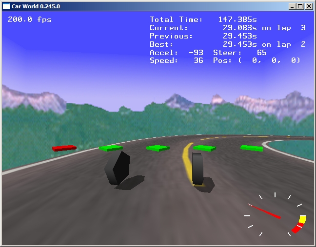
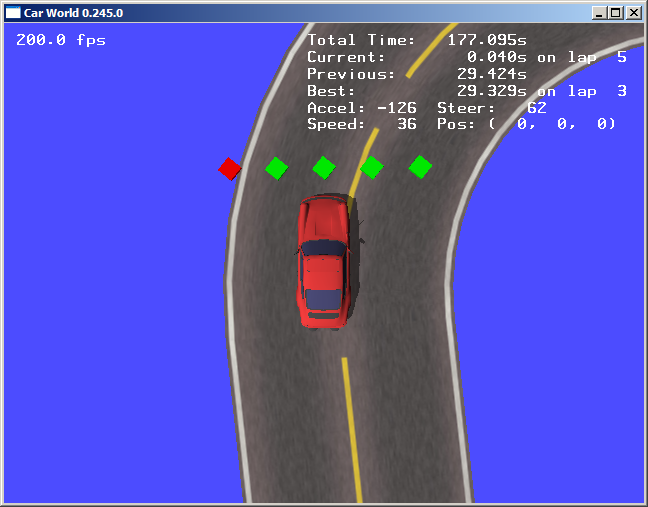
The goal of the Car World game is to guide the car around the track, trying to complete laps as quickly as possible. If the car drives off the track, or if F3 key of the PC keyboard is pressed, the car will reset to the starting point of the track. Below is a screenshot of the default view of the Car World game (on the left), as well as a screenshot of an alternative view (on the right), accessible through pressing F2 key of the PC keyboard.
The car has five sensors in front. These sensors indicate whether the car is approaching the edge of track. For example, on the screenshots above, the leftmost sensor (coloured red) is reporting that it is currently off the track, while the other four sensors (coloured green) are reporting that they are on the track. Your assembly program will need to read the state of these sensors in order to make an informed decision on moving the car. Besides the sensor values, you can also read the current speed of the car, as well as its current position (x, y, and z coordinates).
To move the car you need to inform the Car World game of the desired steering and the acceleration. The text in the Car World window reports the current status of the car to help in debugging your program. To summarize, you are to write a Nios II assembly program that will continuously:
However, bragging rights will be given to groups that achieve best lap times. Hence, try to optimize your code and have some fun while doing it!
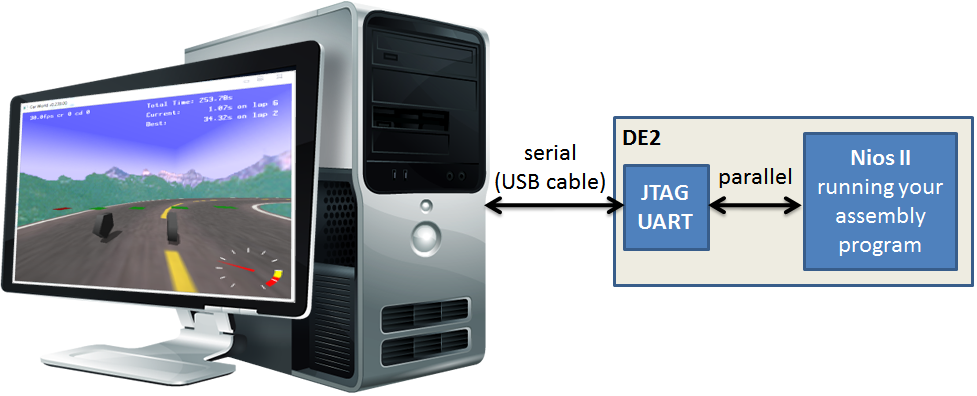
To establish communication between the Car World game and Nios II, you will be using a JTAG-based UART. A UART in general is a device which translates between parallel (many bits at a time) communication to serial (one bit at a time) communication. UARTs are often built for other serial standards such as RS-232 (e.g., "serial port"). In this lab, we will transfer data over the programming cable to avoid using a second cable. JTAG (Joint Test Action Group) is a standard interface often used for programming and debugging chips, and is used by the DE2's USB-Blaster programming. We will also use it for communicating between the Nios system and the PC.
The documentation of the JTAG UART can be found here. As listed in the documentation, bit 15 of the Data Register is a "data valid" bit. To see if data is ready to be received from the UART, one can continually poll the valid bit in a loop, and when it is valid, branch to code that handles the received data. To determine when new data can be written to the UART, one can continually, in a loop, check the available write buffer space in the Control Register[31:16]. When it is non-zero, there is room for more data to be sent to the UART.
The JTAG UART documentation mentioned above describes how to receive or send bytes of data. Now we proceed on describing the actual communication protocol for the Car World program that you will have to obey in order to communicate with the game.
The communication protocol for the Car World program consists of reading and writing packets of data over the JTAG UART. A packet that consists of multiple bytes must be read/written from/to the JTAG UART one byte at a time, and you must implement polling for each packet byte, as discussed above. The first byte of every packet is always the packet type. Packet types range from 0 to 5 and are in details described below. The packet length depends on the type of packet being sent.
There are in total 4 transmit packet types. These packets are sent by your program running on the Nios II to the Car World game.

To get the current state of the sensors and car's speed, send
a one-byte command with value 0x02. The Car
World game will respond by sending the sensor and speed data packet,
described below.

In order to get car's position, send a one-byte command with
value 0x03. The Car World game will
respond by sending the position data packet, described below.
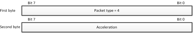
To change the acceleration of the car, you must send a two-byte command to
Car World. The first byte (command type) is 0x04, while
the second byte should be the desired acceleration formatted as a 8-bit
signed number. The acceleration ranges from -127 (full deceleration) to
+127 (full acceleration ahead). It is important to note that an acceleration
of 0 does not mean that the car will not be moving; rather, the car will
continue to move at its current speed. If the speed reaches zero and you
continue to apply a negative acceleration, the car will start moving in
reverse. Unlike for the previous two packet types, the Car World game
sends no response on receiving a packet of this type.
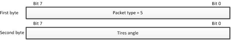
Similarly, to change steering, you must send a two-byte command.
The first byte (command type) is 0x05,
while the second byte should be the desired angle formatted as a 8-bit
signed number. The angle of the tires range from -127 (hard left turn)
through 0 (straight ahead) to +127 (hard right turn). The Car World game
sends no response on receiving a packet of this type.
There are 2 packet types that are sent by the Car World game as a response to transmit packet types described above.
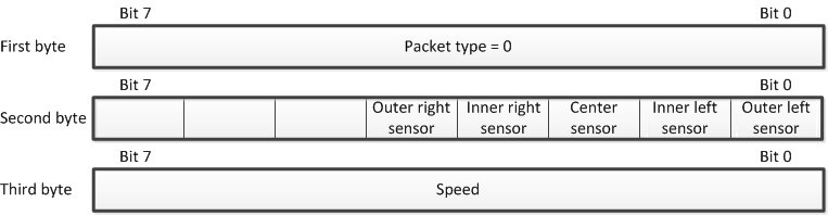
On receiving a packet of type 0x02, the Car World game sends 3 bytes to
the JTAG UART. The first byte is 0x00, while the
other two bytes represent the current value of sensors and the
current speed of the car, respectively. The layout of sensor data is
shown above. "On the track" sensor state is indicated by a value of 1
and "off the track" state is indicated by a value of 0. For example,
the value of the sensor data in the screenshots shown earlier
is 0x1e.
The speed is an 8-bit unsigned number, ranging from 0 (stopped) to 255 (full speed). Note that this is not the velocity of the car, as it only describes how fast the car is moving and not in what direction the car is moving.
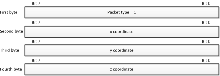
A position data packet consists of 4 bytes, and it is sent by the Car
World game as a response to a packet of type 0x03. The
first byte is 0x01, while the remaining 3 bytes
are 8-bit signed numbers representing x,y, and z coordinates,
respectively. You are not required to use position data but
they may be useful for completing the hard and extreme tracks discussed
below.
Below is a snippet of pseudo-code showing two subroutines for reading sensor and speed data and adjusting the tires angle.
READ_SENSORS_AND_SPEED:
  poll JTAG UART for writing
  write 2 to the JTAG UART (request sensors/speed)

  # Read response (Suggestion: Put this in a function)
  poll JTAG UART for reading
  read JTAG UART
  check that data read is 0
  poll JTAG UART for reading
  read sensor states from JTAG UART
  poll JTAG UART for reading
  read current speed from JTAG UART

  # Decide what to do
  if sensors are 0x1f
    call SET_ANGLE to steer straight
  else if sensors are 0x1e
    call SET_ANGLE to steer right
  else if sensors are 0x1c
    call SET_ANGLE to steer hard right
  else if sensors are 0x0f
    call SET_ANGLE to steer left
  else if sensors are 0x07
    call SET_ANGLE to steer hard left
  else
    hope this doesn't happen
  return

SET_ANGLE:
  poll JTAG UART for writing
  write 5 to the JTAG UART (set steering)
  poll JTAG UART for writing
  write new angle to the JTAG UART
  return
|
car_world.bat. This will:
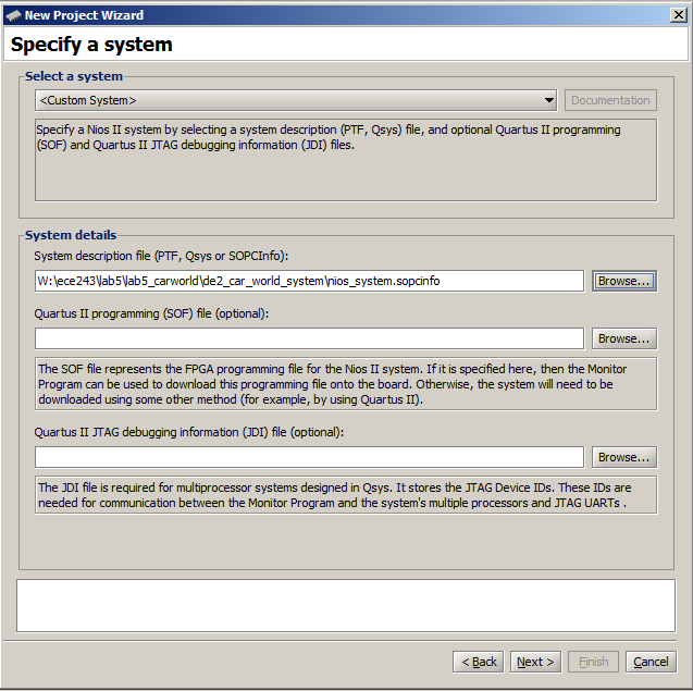
<Custom System>, and specify
the nios_system.sopcinfo file provided in the
directory lab5_carworld/de2_car_world_system directory, as
show in the figure below. Leave all the other fields blank.
For program type, specify the Assembly Program type, and
then add the assembly file you wrote that will control the Car World
game. Set the start offset
for .text and .data sections to
0x400 (You'll need this for Lab 6).
To do these steps outside of DESL labs, besides having Altera Quartus and Altera Monitor program installed, you will need the DE2 board attached to your computer via a USB cable. If you don't have the DE2 board at home, you still must write the required Nios II assembly code and ensure that it at least compiles. For this, skip the first step and just compile your code after completing step 2.
0x00?0x05
followed by 0x9C. What is the meaning of this
information?Be prepared to explain
Demonstrate your working game. In the
directory lab5_carworld/carworld/data/Landscape there are
multiple tracks labelled for various difficulty levels (easy, medium,
hard, and extreme). To change a track:
Actions/Disconnect.
car_world.bat
lab5_carworld/carworld/data/Landscape and
copy the desired track file over the file landscape.txt.
For example, copying landscape_medium_hill_valley.txt
over landscape.txt will switch to the medium track.
car_world.bat again and
select Action/Load option in the Altera Monitor program.
landscape_hard_hill_valley track under 48
seconds. Current rankings here!To complete the easy tracks, the basic approach of just setting the initial speed of the car will suffice. However, due to the surface friction, the car will be slowing down, so you will probably want to adjust the speed accordingly. Moreover, the medium, hard and extreme tracks have hills which will slow down or speed up the car due to gravity, and your program will have to take this into account.
Your TA will record your best lap time on landscape_hard_hill_valley. Don't forget to submit your code.
0x00 to the JTAG
UART in case Car World is waiting for a multi-byte packet.
Car World treats excess 0x00 commands as a no-op.
Memory tab,
go to the memory address 0x10001020, check
the Query All Devices check-box and click
the Refresh Memory button. Then uncheck the check-box.
This is equivalent to reading the UART receive FIFO data until the FIFO is empty.