The | in the next field indicates which channel
will represent the label name.
By default each label has only one
channel.
To group more then one channel under one label,
do the following;
- Use the ARROW KEYS to select the label.
- Use the ARROW KEYS move to the channel select field.
- Press Select, until the | appears for
each channel to be grouped together.
This is typically done to create a bus
eg address , data.
Below are the LEAD colours on the end of the ribbon cable and the channel number
represented by them at default power up.
The	 GRAY 		leads are used for GROUND

The	 BLACK 		leads is used for channel "0"

The	 BROWN 		leads is used for channel "1"

The	 RED 		leads is used for channel "2"

The	 ORANGE 	leads is used for channel "3"

The	 YELLOW 	leads is used for channel "4"

The	 GREEN 		leads is used for channel "5"

The	 BLUE 		leads is used for channel "6"

The	 VIOLET 	leads is used for channel "7"

The	 BLACK 		leads is used for channel "8"

The	 BROWN 		leads is used for channel "9"

The	 RED 		leads is used for channel "10"

The	 ORANGE 	leads is used for channel "11"

The	 YELLOW 	leads is used for channel "12"

The	 GREEN 		leads is used for channel "13"

The	 BLUE 		leads is used for channel "14"

The	 VIOLET 	leads is used for channel "15"
Here is an example of what the menu looks like.
*note* this is
an example of a 4 channel Logic Analyzer. Ours are 2 Channel
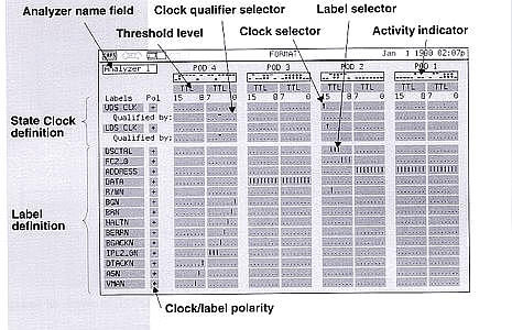 The label name address and data are examples of a
"bus".
The label name address and data are examples of a
"bus".
The label name bgn and brn are examples of
individual signals.
Setting up TRIGGER
- Select the TRACE Key.
The TRACE MENU
will appear on the screen.
- The menu User-defined specifies the trigger L1.
The
default trigger is set to TimeWord.
- Use the ARROW KEYS select TimeWord ,at the top of the screen
beside L1.
- Press the SELECT KEY.
- Another menu will appear with the following options;
(Wait forever,
State word,/State word,Immediate,Range,/Range,Clock,State
Expression)
These trigger menus are used for State analysis.
(Glitch,Edge,Timeword,Time filters,Timing expression,Timeout)
These trigger menus are used for Timing analysis.
For most
applications in the lab the only menus that will be used
are
(TimeWord,Edge and sometimes glitch).

At the bottom of the screen is the trigger expression for
TimeWord.
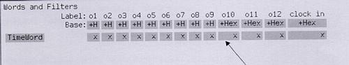
Under the field Label are the names of the labels defined in
the FORMAT menu.
Beside the field
Base is the format of the signal. The Default is
HEX.
To change this use the ARROW KEYS and the SELECT
KEY.
The other options are:
- BINARY
- OCTAL
- DECIMAL
- ASCII
Beside the field TimeWord is the trigger
expression.
- X means don't care
- 1 means trigger active High Level
- 0 means trigger active Low Level
Example of setting up a Trigger
Before continuing do the follow;
Change labels to the following names
following the procedure described under changing labels
	a	----> clk
	b	----> as
	c	----> uds
	d	----> lds
	e	----> dtack
	f 	----> r/w
	g	----> a23
	h	----> a22
With POWER OFF connect the leads to the
68000_BUS header on the ULTRA GIZMO header as described
below.
This is the 60 pin header on the left side of the board above
the two audio connectors.
*note* When counting pins, the pins on
the left side of the header are odd values and the pins on the right side of the
header are even.
1 2
3 4
5 6
. .
57 58
59 60
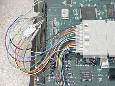
Leads 68000_BUS
--------------------------
GRAY pin1
BLACK pin2
BROWN pin30
RED pin32
ORANGE pin34
YELLOW pin28
GREEN pin27
BLUE pin26
VIOLET pin25
The connections should look like the picture below
POWER UP the ULTRA GIZMO board and press the RESET switch.
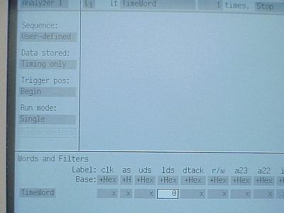
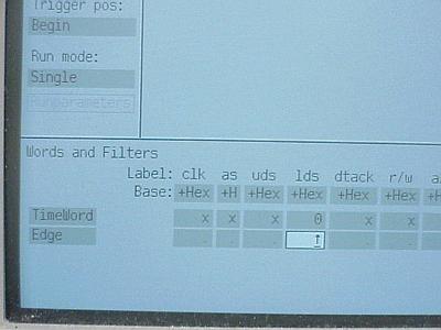
Example 1 setting up TimeWord
- Select TRACE KEY.
- Using the ARROW KEYS move around the screen until the label below
lds is Hi-lited.
The label lds is at the bottom of the
screen in the trigger expression TimeWord.
- Using the Alphabetic KEYS select 0.
The 0 will
appear inside the label Hi-lited.
The screen information should
look like the picture below.
- Press the RUN Key.
- The Display screen will appear. Your display information should look
similar to the picture below.
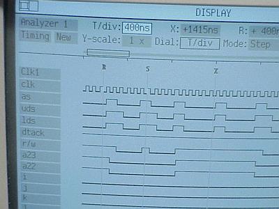
- Use the ARROW KEYS or the DIAL to scroll through the
different menus at the top of the screen.
- T/div: indicates the time per division, the smaller the time
value the more detailed the information, the larger the time value that more
information that will be captured.
- X: moves the X cursor
To scroll the X cursor use
the DIAL or press SELECT and select from the menu where the
cursor should go; br> Begin- to the beginning of the captured
signals.
Center- to the centre of the captured
signals.
End- to the end of the captured signals.
R
cursor- moves to the location where R cursor is.
S cursor-
moves to the location where S cursor is.
Trigger- moves to the
location where Trigger is.
Time- moves to the time location
specified .
- R: moves the R cursor.
Use scroll or dial as
explained above.
- S: moves the S cursor.
Use scroll or dial as
explained above.
Y-scale: changes the Y scale size use SELECT and the ARROW
to change the scale size.
Mode: selects the mode in which the cursor moves across the screen.
- Scroll scrolls across the screen as the DIAL is rotated.
- Edge scrolls from edge to edge as the DIAL is rotated.
- Division scrolls according to T/div as the DIAL is
rotated.
- Page scrolls from page to page as the DIAL is rotated.
- Level scrolls from signal level change either a High to a low or a
Low to a high as the DIAL is rotated.
Example 2 setting up trigger using EDGE
- Press the TRACE KEY.
- Using the ARROW KEYS select TimeWord at the top of the
screen.
- Press the SELECT Key.
- A new menu should appear with different trigger patterns.
- Using the ARROW KEYS select Edge.
- Press the SELECT Key.
- At the bottom of the screen another trigger pattern will appear with the
label Edge.
- Using the ARROW KEYS select lds at the bottom of the screen
for the trigger pattern edge.
- Keep pressing SELECT until an UP ARROW appear for lds.
The window should appear similar to the picture below.
- Press the RUN Key.
- Follow the procedures described before for TimeWord to analyse the
information.
Now hook up your circuit and do some timing analysis.
TOP
