In this lab you will learn how to use the Parallel Interface (JP1/JP2 connectors on the DE2 board) to communicate with another piece of hardware, called the Lego controller. The Lego controller connects to motors and sensors that physically integrate with the classic children's Lego kits. You will also learn how to use the Timer peripheral on the DE2 computer, so that you can create known and precise delay intervals.
You will build a self-balancing device made from Lego which will be controlled by the Lego controller and the DE2 Nios II processor. In Part 1 of this lab you will implement a basic balancing algorithm to read the sensors and control the motor. In Part 2 you will improve your algorithm by slowing down the motor. This involves using the timer to implement a technique called Pulse Width Modulation (PWM).
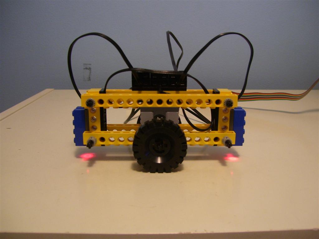
The Balancing Device Construction Manual describes how you can build the self-balancing device shown in the figure below. The device consists of a frame and a Lego motor balanced on a single axle with two wheels. In addition, at each end of the frame there is a Lego sensor that faces towards the ground. Each sensor measures its distance from the ground based on the reflection of a built-in LED. The closer the sensor is to the ground, the more light it senses, and the higher the value it reports. By examining the values of both sensors, the device can determine if it is tilting in one direction or another. The goal of the lab is to receive this information, and determine how much to roll the device, using the motor, in the direction that will correct that tilt.
In Part 1 you will write an assembly program that will read the values of the two sensors. If the values of the sensors indicate the device is tilting, you should drive the motor either clockwise or counterclockwise, so that the device rolls in the direction that will correct that tilt. Otherwise, if the sensor values indicate the device is not tilting, you can turn off the motor. One decision you will have to make in the design of your program is how much of a tilt (in either direction) the device should tolerate before it tries to correct it. You are encouraged to experiment with different levels of tolerance and choose one that seems to work the best.
The Lego Controller Device Documentation describes how you can control the motors and read the sensor values. As described in that document, the sensor interface works either in value mode or state mode. For this lab, use the value mode of the sensor interface.
Once you test your code from Part 1, you will see that your device is not able to achieve a perfect balance. Instead it rapidly oscillates back and forth. This is because the motor is much stronger than we want it to be, which causes it to "overcompensate" when trying to correct a tilt. We now want to reduce the strength of the motor to remove this "overcompensation" so that your device will be able to balance itself.
Without making any physical changes to your Lego setup, you will slow down/weaken the motor by using a technique called Pulse Width Modulation (PWM). The idea is to turn the motor on and off rapidly to reduce the average motor power. You will do this by repeatedly turning the motor on for X cycles and then off for Y cycles.
You will use the
Timer
peripheral to accurately time the X and Y cycles. Although this
could be done using program-based delay loops, to receive any marks
you are required to use the timer as described here. Write a Nios II
assembly language subroutine that, when called with a
parameter, N, waits for N Timer cycles before
returning, using the timer peripheral. Incorporate this subroutine into
your code for the Part I program to implement the pseudo-code
described below. This must be a proper subroutine (call, return, parameter passing, etc.)
/* NOTE: This is meant as pseudo-code, you are to use assembly */ Turn Motor ON Delay 50000 cycles using the Timer Turn Motor OFF Delay 50000 cycles using the Timer |
The pseudo-code uses a 50% duty cycle (X=50000, Y=50000). This is a good starting point but you are encouraged to experiment with different values of the duty cycle (X/(X+Y)) to change the strength of the motor.
The ultimate goal of this lab is for your device to be able to balance itself perfectly on its two wheels as quickly as possible.
Be prepared to answer any questions about your code, and about how the Lego motors, the sensors and the timer work.