The purpose of this lab is to familiarize yourself with the use of interrupts. Interrupts are a very powerful mechanism that can be used to support multitasking, handling of exceptional conditions (i.e., unexpected results during calculation such as a division by zero), emulation of unimplemented (in hardware) instructions, single-step execution for debugging, and operating system calls/protection among others.
In this lab, you will extend your solution to Lab 5 to communicate with two new devices, the JTAG UART and timer, using interrupts, while controlling the Car World game. Specifically, you are to display the current speed of the car or the current state of the sensors in the Monitor Program terminal, using key presses to switch between these two values:
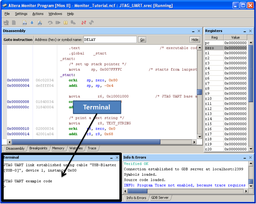
The characters sent to the terminal JTAG UART will be displayed on the
terminal window. For example, sending
byte 0x34 to the terminal JTAG UART will display character
'4'. In the other direction, typing in the terminal window will send data to the
terminal JTAG UART (also using ASCII code).
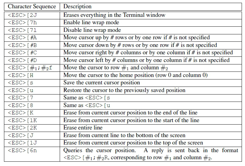
The Monitor Program's terminal interprets certain character sequences ("escape
codes") as commands that control the terminal's output, such as clearing the window or moving the cursor.
These escape codes can be found on page 24 of
the Monitor
Program Tutorial. The table is reproduced
below. <ESC> represents a character with value
27 (0x1b). For example, sending the four-character
sequence <ESC>[2K (1b 5b 32 4b) will erase an entire line.
Interrupts must be enabled in three places:
ienable control register
(ctl3). For example, the Timer
is associated with IRQ line 0, so you unmask this interrupt line by
setting bit 0 of ienable to high.
status
(ctl0) register.
ipending (ctl4) control register
tells you which IRQ line(s) are requesting an interrupt. For
example if bit 0 of ipending is high you know that the Timer
is requesting an interrupt. Multiple interrupts may
happen simultaneously, therefore multiple bits of the
register ipending can be 1 at the same time.
When a device interrupt occurs, the processor jumps to the ISR. However, we
need to be able to return to the code that was executing before interrupt
happened. The processor saves the address of the instruction after
the instruction that was aborted in the
ea (exception
address) register. Therefore you must adjust the saved
address in ea so that the processor re-executes the
aborted instruction, by subtracting 4
from ea (each instruction is 4 bytes), then executing
the eret (exception return) instruction to return to
normal program execution.
When a processor is interrupted, it causes the processor to jump to
location 0x00000020. Your interrupt service routine must be located at this exact location. To do
this, place the ISR code in the .exceptions section (rather than the usual ".text" section).
The .exceptions section always starts at location 0x20.
Use the code below as a template.
.section .exceptions, "ax" myISR: [interrupt service routine starts here at 0x20] |
When compiling your code, you have to ensure that sections
.exceptions (your ISR) and .text
(the rest of the code) are placed in non-overlapping memory regions.
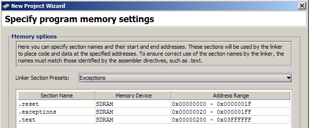
To do this, change the "Linker Section Preset" to "Exceptions" when creating a new project
to change the starting locations of the various sections to suitable
values (.exceptions to 0x20 and .text to 0x200 by default).
Overlapping sections
result in an error similar to "section .exceptions loaded at [...] overlaps section .text loaded at [...]"
After compiling your code, verify that your ISR was actually
placed at address 0x00000020. You can do this by
looking at the disassembly in the Monitor program. Typos are a common reason for the ISR to be placed incorrectly.
ff201000) documentation.ff202000) documentation.Be prepared to answer any questions about interrupts on Nios II.